Cisco VSS
Virtual Switching System
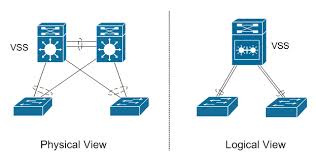
VSS allows 2 physically separate switches to operate and to be configured as 1 single logical switch.
VSS creates a more redundant and more resilient core and allows for more efficient use of bandwidth in closet switch uplinks by using MEC's (Multi-chassis Etherchannels) between the Edge and Distribution or Core environments. The VSS switches use VSL's (Virtual Switch Links) between them for both forwarding traffic and Control Plane traffic. In VSS, the Data Planes of both VSS members are active at the same time so they can both forward traffic, but also take over for all functions should one of the members fail, providing both SSO (Stateful switchover) and NSF (Non-stop forwarding).
VSS can be implemented on 4500E, 4500X, 6500 and 6807 series switches.
In this example, the VSL link is configured between the SUP modules of (2) 6807 switches, however any 10Gb ports can be used, including line-card 10Gb ports.
VSS Configuration - switch 1
Switch virtual domain 1 <-- begins the VSS configuration on the switch
Switch 1 <-- identifies the switch as switch one of two members
Switch 1 priority 110 <-- Optional - sets a priority on this switch of 110, this switch will be the primary switch between the two
!
Interface port-channel 201 <-- the VSL's need their own dedicated port-channels between the VSS members
switch virtual link 1 <-- identifies this port-channel as one side of the VSL
!
inter ten 3/4
channel-group 201 mode on <-- Add's this port to the port-channel
inter ten 4/4
channel-group 201 mode on
VSS Configuration - switch 2
Switch virtual domain 1 <-- begins the VSS configuration on the 2nd switch
Switch 2 <-- identifies the switch as switch number 2 of two members
Switch 2 priority 100 <-- Optional - sets a priority on this switch of 100, Lower than switch 1 so this will be the standby switch
!
Interface port-channel 202 <-- This is the other side of Po1 on switch 1, but needs to be configured as a different port-channel number
switch virtual link 2 <-- identifies this port-channel as the other side of the VSL
!
inter ten 3/4
channel-group 202 mode on <-- Add's this port to the port-channel
inter ten 4/4
channel-group 201 mode on
VSS Configuration - switch 1 (Cont'd)
switch convert mode virtual <-- tells the switch to reload and merge with the other VSS member
VSS Configuration - switch 2 (Cont'd)
switch convert mode virtual <-- command must be run on both members of the VSS
Switches will then prompt to save config and then reboot into VSS mode
***Note: If switches do not save the "switch 1" or "switch 2" command in the CLI, you may need to enter "switch set switch_num 1" and "switch set switch_num 2" commands in the CLI to set them in ROMMON. You can verify switch ROMMON settings from the CLI by issuing the command "switch read switch_num".
During the reboot you will see on Switch 1:
System detected Virtual Switch configuration...
Interface TenGigabitEthernet 1/3/4 is member of PortChannel 201
Interface TenGigabitEthernet 1/4/4 is member of PortChannel 201
And on Switch 2:
System detected Virtual Switch configuration...
Interface TenGigabitEthernet 2/3/4 is member of PortChannel 202
Interface TenGigabitEthernet 2/4/4 is member of PortChannel 202
VSS Verification Commands
Show switch virtual redundancy
show switch virtual role
Show switch virtual link
Show switch virtual link port-channel
Virtual Switching System
VSS allows 2 physically separate switches to operate and to be configured as 1 single logical switch.
VSS creates a more redundant and more resilient core and allows for more efficient use of bandwidth in closet switch uplinks by using MEC's (Multi-chassis Etherchannels) between the Edge and Distribution or Core environments. The VSS switches use VSL's (Virtual Switch Links) between them for both forwarding traffic and Control Plane traffic. In VSS, the Data Planes of both VSS members are active at the same time so they can both forward traffic, but also take over for all functions should one of the members fail, providing both SSO (Stateful switchover) and NSF (Non-stop forwarding).
VSS can be implemented on 4500E, 4500X, 6500 and 6807 series switches.
In this example, the VSL link is configured between the SUP modules of (2) 6807 switches, however any 10Gb ports can be used, including line-card 10Gb ports.
VSS Configuration - switch 1
Switch virtual domain 1 <-- begins the VSS configuration on the switch
Switch 1 <-- identifies the switch as switch one of two members
Switch 1 priority 110 <-- Optional - sets a priority on this switch of 110, this switch will be the primary switch between the two
!
Interface port-channel 201 <-- the VSL's need their own dedicated port-channels between the VSS members
switch virtual link 1 <-- identifies this port-channel as one side of the VSL
!
inter ten 3/4
channel-group 201 mode on <-- Add's this port to the port-channel
inter ten 4/4
channel-group 201 mode on
VSS Configuration - switch 2
Switch virtual domain 1 <-- begins the VSS configuration on the 2nd switch
Switch 2 <-- identifies the switch as switch number 2 of two members
Switch 2 priority 100 <-- Optional - sets a priority on this switch of 100, Lower than switch 1 so this will be the standby switch
!
Interface port-channel 202 <-- This is the other side of Po1 on switch 1, but needs to be configured as a different port-channel number
switch virtual link 2 <-- identifies this port-channel as the other side of the VSL
!
inter ten 3/4
channel-group 202 mode on <-- Add's this port to the port-channel
inter ten 4/4
channel-group 201 mode on
VSS Configuration - switch 1 (Cont'd)
switch convert mode virtual <-- tells the switch to reload and merge with the other VSS member
VSS Configuration - switch 2 (Cont'd)
switch convert mode virtual <-- command must be run on both members of the VSS
Switches will then prompt to save config and then reboot into VSS mode
***Note: If switches do not save the "switch 1" or "switch 2" command in the CLI, you may need to enter "switch set switch_num 1" and "switch set switch_num 2" commands in the CLI to set them in ROMMON. You can verify switch ROMMON settings from the CLI by issuing the command "switch read switch_num".
During the reboot you will see on Switch 1:
System detected Virtual Switch configuration...
Interface TenGigabitEthernet 1/3/4 is member of PortChannel 201
Interface TenGigabitEthernet 1/4/4 is member of PortChannel 201
And on Switch 2:
System detected Virtual Switch configuration...
Interface TenGigabitEthernet 2/3/4 is member of PortChannel 202
Interface TenGigabitEthernet 2/4/4 is member of PortChannel 202
VSS Verification Commands
Show switch virtual redundancy
show switch virtual role
Show switch virtual link
Show switch virtual link port-channel
